RTO Regenerative Combustion Equipment
RTO Regenerative Combustion Equipment
Regenerative Thermal Oxidizer (RTO): The RTO primarily consists of a combustion chamber, combustion system, regenerative chambers, ceramic heat exchangers (thermal storage media), and switching valves. It is a highly efficient organic waste gas treatment device that operates by oxidizing combustible gases into corresponding oxides and water at high temperatures (760°C–850°C), thereby purifying the exhaust gas. The system also recovers heat released during the decomposition process, achieving a destruction efficiency of over 99% and a heat recovery efficiency exceeding 95%.
Working Process Description::
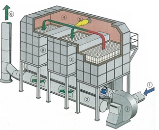
The RTO operates with three regenerative chambers labeled A, B, and C. The system consists of one intake manifold (with three inlet ports: A1, B1, C1) and one exhaust manifold (with three outlet ports: A2, B2, C2). During operation, it maintains a “single-inlet-single-outlet” mode, ensuring all exhaust gases undergo high-temperature combustion purification.
Operation Process:
- Exhaust gas enters through chamber A (inlet A1), where it is preheated by the regenerative media before entering the combustion chamber for oxidation at 760-850°C.
- The purified hot gas then passes through chamber B (which was cooled in the previous cycle), transferring heat to the regenerative media before being discharged through outlet B2.
- Chamber B absorbs substantial heat during this process (for preheating gas in the next cycle).
- Typically, the exhaust gas temperature is 35-50°C higher than the inlet temperature.
Cycle Transition:
Upon cycle completion, the system switches valves to initiate a new cycle:
- Exhaust gas now enters through chamber B (inlet B1)
- Purified gas exits through chamber C (outlet C2)
- Simultaneously, fresh air purges residual gases from chamber A via a purge fan
This alternating three-chamber operation ensures:
- Destruction efficiency exceeding 99%
- Continuous heat recovery (≥95% efficiency)
- Stable operation with minimal energy consumption
The chambers rotate through heating, purging, and cooling phases in sequence, maintaining optimal thermal efficiency and emission control performance.
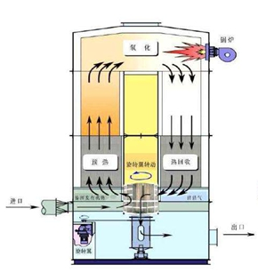
Rotary RTO Operation Principle:
The rotary RTO features partition plates within the regenerative heat exchanger, dividing the ceramic bed into 12 independent sectors.
Process Flow:
Exhaust gas enters through the bottom gas distributor into the preheating zone, where it is heated to the required temperature before rising to the top combustion chamber for complete oxidation.
The purified high-temperature gas exits the combustion chamber and flows into the cooling zone, transferring its heat to the ceramic media before being discharged through the gas outlet distributor.
The ceramic media in the cooling zone absorbs and stores thermal energy (for preheating incoming gas in the next cycle).
To prevent untreated exhaust from bypassing oxidation and entering the clean gas outlet, a dedicated purge sector is positioned before the outlet zone, where clean air is injected to flush out residual contaminants.
Continuous Cyclic Operation:
As the rotary valve rotates, each sector sequentially undergoes:
Cooling (heat recovery from purified gas)
Purging (removal of residual pollutants)
Heating (preheating incoming exhaust gas)
Blind zone (transition phase)