Activated Carbon Adsorption Tower
Activated Carbon Adsorption Tower
An activated carbon adsorption tower is an environmental protection device designed to treat organic waste gases and odors. It primarily utilizes the adsorption capacity of activated carbon to remove organic pollutants and odorous substances from industrial exhaust streams.

Sources of Organic Waste Gases
Organic waste gases primarily originate from stationary sources and mobile sources:
- Mobile sources: Emissions from petroleum-fueled vehicles (e.g., cars, ships, aircraft).
- Stationary sources: Diverse industrial activities, including:
- Petrochemical processes and storage facilities
- Operations involving organic solvents, such as:
› Spray painting › Printing › Metal degreasing
› Adhesive production › Pharmaceuticals › Plastics
› Coatings manufacturing › Rubber processing
Environmental and Health Impacts of Organic Compounds
Volatile organic compounds (VOCs) in waste gases are significant pollutants. Numerous industries—including coating, printing, footwear manufacturing, and chemical production—generate substantial VOC emissions during industrial processes.
Environmental and Health Impacts of VOC Emissions
The release of volatile organic compounds (VOCs) into the atmosphere leads to the following consequences:
- Photochemical Pollution
VOCs act as precursors to photochemical reactions. Under sunlight, they react with NOx and other airborne chemicals to form ozone and photochemical smog, a primary contributor to atmospheric pollution. - Human Health Effects: Photochemical smog irritates eyes and respiratory systems; Certain VOCs emit strong odors, reducing air quality and causing discomfort at elevated concentrations.
- Toxic Hazards:
- Carcinogenic VOCs (e.g., benzene, chlorinated hydrocarbons) may cause cancer or severe diseases upon prolonged exposure.
- Benzene damages bone marrow and is a known carcinogen.
- Toluene and xylene strongly affect the central nervous system.
- Vinyl chloride is a confirmed carcinogen.
- Industrial incidents: Multiple fatalities have occurred in shoe manufacturing due to “three benzene” (benzene, toluene, xylene) poisoning.
- Paints/solvents predominantly contain toluene, xylene, and other toxic organics.
- Carcinogenic VOCs (e.g., benzene, chlorinated hydrocarbons) may cause cancer or severe diseases upon prolonged exposure.
- Historical Cases
- Japan (1965): Repeated photochemical smog events in major cities.
- Los Angeles (1966): Severe smog crises with documented health impacts.
The significant environmental hazards and severe health threats posed by VOCs (Volatile Organic Compounds) have garnered high-level attention from governments worldwide.
- The U.S. Environmental Protection Agency (EPA) identifies over 300 pollutants as VOCs in its regulated substances list.
- The U.S. Clean Air Act (1990) mandated a 90% reduction in emissions for 189 toxic chemicals, 70% of which are VOCs.
China implemented strict VOC regulations as early as January 1, 1997, under the “Integrated Emission Standard of Air Pollutants” (GB16297-1996). This standard imposes stringent limits on key VOCs like benzene, toluene, xylene, and vinyl chloride, as shown in Table 1.1 below:
| VOCs | Maximum Allowable Emission Concentration (mg/m³) |
| Benzene | 12 |
| Toluene | 40 |
| Xylene | 70 |
| Vinyl Chloride | 36 |
Note: These standards apply to new pollution sources.
Current Status and Advances in Organic Waste Gas Treatment Technologies
The sources of organic waste gases are diverse, with varying production and emission patterns. Consequently, treatment technologies also vary significantly, each with distinct advantages and limitations. Selecting the appropriate method based on specific conditions is crucial for effective organic waste gas management.
Classification of Treatment Technologies
Organic waste gas treatment methods fall into two main categories: recovery methods and destruction methods.
- Recovery Technologies
- Adsorption (e.g., activated carbon)
- Absorption (liquid scrubbing)
- Condensation
- Membrane separation
- Pressure swing adsorption (PSA)
- Destruction Technologies
A. Physicochemical Methods
- Thermal destruction (incineration, catalytic combustion)
- Photolysis
- Corona discharge
- Ozone decomposition
B. Biological Methods
- Biofilters
- Biotrickling filters
- Bioscrubbers
- Membrane bioreactors
- Activated sludge processes
Technology Comparison & Challenges
Activated carbon adsorption:
- Efficiency: >95% removal rate.
- Limitations: High operational costs without regeneration; steam regeneration requires complex infrastructure, and solvent-water mixtures have low reuse value. Adsorption capacity declines after 2–3 years.
Liquid absorption:
- Efficiency: 60–80%, with risks of secondary pollution.
Catalytic combustion:
- Efficiency: >95%, but only viable for high-concentration, small-volume, high-temperature waste gases. Energy-intensive for preheating.
Emerging Solutions
The adsorption-catalytic combustion hybrid system is widely adopted, typically using granular or honeycomb carbon. However, conventional setups face challenges:
- Large adsorbent beds (requiring dual alternating chambers for continuity).
- Long switching cycles (≥1 day), leading to bulky equipment and high costs.
- Risk of combustion/explosion due to adsorbed heat accumulation.
Innovations:
- Modular multi-unit分流 systems with activated carbon fiber (ACF) adsorbents.
- PLC automation for continuous operation, enhancing safety and efficiency.
Analysis and Comparison of Various Purification Methods
To address the pollution caused by organic waste gases, the most fundamental solution lies in process reform. However, transitioning to non-toxic coatings and solvents cannot be achieved immediately in current production, as benzene-based solvents remain widely used. Therefore, waste gas purification must be implemented.
Below is a comparative analysis of the three most commonly used purification methods in China:
| Purification Method | Advantages | Disadvantages |
| Activated Carbon Adsorption | 1. Suitable for high airflow, low-concentration organic waste gases; 2. Solvent recovery possible; 3. No heating required; 4. High purification efficiency with low operating costs. | 1. Requires pre-treatment of waste gases; 2. Only effective for low concentrations; 3. Bulky equipment, requiring large space. |
| Catalytic Combustion | 1. Simple equipment, low investment, easy operation, and compact footprint; 2. Heat can be recycled; 3. Effective for high- concentration waste gases. | 1. High catalyst cost; 2. Risk of catalyst poisoning and surface contamination, leading to reduced efficiency. |
| Liquid Absorption | 1. Simple process, with inexpensive absorbents. 2. No pre-treatment required; 3. Fast installation and small footprint. | 1. High post- treatment costs; 2. Selective effectiveness depending on solvent composition. |
Design Task Description
Design Task
The project involves the engineering design of an activated carbon adsorption system for treating industrial organic waste gas with a flow rate of 20,000 m³/h. Key design components include:
- Waste gas treatment process
- Main equipment selection & non-standard equipment design
- Pipeline transportation system design
- Adsorbent regeneration system design
Deliverables Required:
- Printed and electronic versions of the design specification.
- Translated documents and photocopies of the original text.
- Design drawings, including:
- Layout plan
- Process flow diagram (PFD)
- Key structure drawings
- Pipeline arrangement plan
Design Input Parameters
- Flow rate: 20,000 m³/h
- Temperature: 35°C
- Exhaust pressure: 101.325 kPa
- Inlet concentrations:
- Benzene: 100 mg/m³
- Toluene: 80 mg/m³
- Xylene: 100 mg/m³
Design Output Standards
Compliance with Guangdong Provincial Standard Emission Limits of Air Pollutants (DB44/27-2001) – Level 1 Emission Standards.
Table: Design Output Concentration (Unit: mg/m³)
| Parameter | Benzene | Toluene | Xylene |
| Outlet Concentration | ≤12 | ≤40 | ≤70 |
Design Objectives
- Strict adherence to national environmental protection regulations to ensure all pollutants meet national and regional emission standards.
- Zero secondary pollutants generated after treatment.
- Reliable operation, high treatment efficiency, and easy maintenance.
- Energy-efficient, low operating costs, minimized capital investment, compact footprint, and user-friendly operation.
- Flexible process design and equipment selection to accommodate operational adjustments.
Process Description
Process Selection
The selection of treatment technology should be based on a comprehensive evaluation of factors such as gas volume, purification requirements, recovery feasibility, equipment construction, and operational economics. In practice, close coordination with the production process is essential to maximize resource utilization.
Currently, there are three common methods for organic waste gas treatment globally:
- Liquid Absorption
- Purification efficiency: 60–80%
- Suitable for low-concentration, high-volume organic waste gases.
- Drawback: Risk of secondary pollution.
- Catalytic Combustion
- Purification efficiency: 95%
- Suitable for high-concentration, low-volume organic waste gases.
- Drawbacks
- Strict gas composition requirements.
- High operating costs due to fuel consumption for preheating.
- Activated Carbon Adsorption
- Purification efficiency: 99.2–99.3%
- Globally recognized as the most mature and reliable technology for high-volume, low-concentration organic waste gases.
- Challenges:
- Long process flow.
- High operational costs.
- Dependence on a stable steam supply for regeneration.
To address these limitations while aligning with the requirements of this project, a fixed-bed activated carbon adsorption system is adopted for industrial organic waste gas purification, utilizing honeycomb activated carbon as the adsorbent.
Process Flow
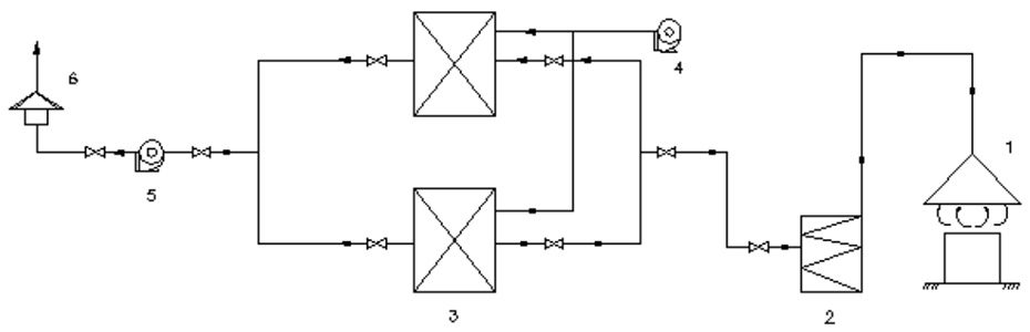
Note: 1. Air collection hood; 2. Demister filter; 3. Fixed activated carbon adsorption bed; 4. Steam supply fan; 5. Centrifugal fan; 6. Exhaust hood.
Organic Waste Gas Treatment Process Flow Diagram
This treatment system features a highly compact adsorption-desorption integrated design. The waste gas generated during production primarily contains benzene, toluene, xylene, and other aromatic compounds. Based on the characteristics of these benzene-series substances, the system employs activated carbon as the adsorbent for waste gas treatment.
The system is typically equipped with two or more adsorption beds operating in rotation. When the organic compounds adsorbed by one bed reach the predetermined capacity, the process automatically switches to another bed for continuous purification, while the saturated bed undergoes steam-assisted thermal desorption for regeneration. Notably, most of the heat energy from the tail gas is recycled to facilitate adsorbent regeneration, achieving effective waste heat utilization.
Process Flow:
- Volatile organic compounds (VOCs) emitted during production are extracted by a centrifugal fan and directed to the adsorption tower.
- The gas flows right-to-left and bottom-to-top through the activated carbon filtration layer for treatment.
- Purified gas is discharged into the atmosphere via the exhaust pipe.
Design and Calculation
Adsorption Principle
When treating fluid mixtures with porous solid materials, certain components in the fluid may be attracted to and concentrated on the solid surface. This phenomenon is called adsorption. In waste gas treatment, the adsorbed substances are gaseous pollutants, referred to as adsorbates, while the porous material is called the adsorbent.
After adsorption occurs, some adsorbed components may detach from the adsorbent surface, a process known as desorption. Over time, as the adsorbent surface becomes saturated, its adsorption capacity significantly declines, making it unable to meet purification requirements. At this stage, measures must be taken to remove the adsorbed substances (desorption) and restore the adsorbent’s capacity—a process called adsorbent regeneration. In practical applications, the cyclic adsorption-regeneration-adsorption process enables continuous removal of pollutants and recovery of valuable components from waste gases.
The adsorption capability arises from residual attractive forces on the porous solid adsorbent’s surface. Depending on the interaction forces between the adsorbent and adsorbate, adsorption can be classified into:
- Physical adsorption (physisorption, driven by van der Waals forces)
- Chemical adsorption (chemisorption, involving chemical bonding)
The same pollutant may undergo physical adsorption at lower temperatures and chemical adsorption at higher temperatures, or both simultaneously, with no strict boundary between the two. Key differences are summarized in Table below:
Differences Between Physical Adsorption and Chemical Adsorption
| Property | Physical Adsorption | Chemical Adsorption |
| Adsorption Force | van der Waals forces | Chemical bonding |
| Adsorption Layers | Monolayer or multilayer | Monolayer only |
| Adsorption Heat | Small (≈ heat of liquefaction) | Large (≈ heat of reaction) |
| Selectivity | None or weak | Strong |
| Reversibility | Reversible | Irreversible |
| Adsorption Equilibrium | Easily achieved | Difficult to achieve |
The adsorption force between the adsorbent and adsorbate is relatively weak. When the partial pressure of the adsorbate in the gas decreases or the temperature rises, desorption readily occurs. Industrial adsorption processes precisely utilize this reversibility to regenerate adsorbents and recover adsorbates for reuse.
Adsorption Mechanism
Adsorption and desorption are reversible processes. When a fresh adsorbent is used to adsorb the adsorbate from a gas, there is initially no desorption of the adsorbate since none is present on the adsorbent surface. However, as adsorption proceeds, the amount of adsorbate on the adsorbent surface gradually increases, leading to the onset of desorption. Over time, the desorption rate continues to rise. Macroscopically, however, the amount of adsorption still exceeds the amount of desorption within the same time frame, so the overall process is considered adsorption. When the amount of adsorption equals the amount of desorption in the same period, adsorption and desorption reach dynamic equilibrium, at which point it is referred to as adsorption equilibrium. At equilibrium, the concentrations of the adsorbate in the fluid and on the adsorbent surface no longer change, and macroscopically, the adsorption process ceases. The concentration of the adsorbate in the fluid at equilibrium is called the equilibrium concentration, while its concentration on the adsorbent is termed the equilibrium adsorption capacity.
When the adsorbate and adsorbent remain in contact for an extended period, adsorption equilibrium is eventually achieved. The equilibrium adsorption capacity represents the maximum adsorption capacity of the adsorbent for the adsorbate, also known as the static adsorption capacity fraction or static activity fraction, denoted as 𝑋𝑡, which is dimensionless. This parameter is crucial in design and production. At adsorption equilibrium, the relationship between the concentrations of the adsorbate in the gas and solid phases is typically represented by an adsorption isotherm. Adsorption isotherms are usually plotted based on experimental data and are often described using various empirical equations.
Adsorption Isotherm and Adsorption Isotherm Equation
The equilibrium adsorption capacity represents the maximum amount of adsorbate that an adsorbent can adsorb. Its value is of great significance for adsorption operations, design, and process control. At adsorption equilibrium, there exists a functional relationship between the equilibrium adsorption capacity, the concentration of the adsorbate in the fluid, and the adsorption temperature. This relationship is referred to as the adsorption equilibrium relationship, which is generally determined experimentally but can also be expressed using empirical equations.
Adsorption Isotherm
In gas adsorption, the equilibrium relationship can be expressed as: A = f(p, T)
where:
- A = equilibrium adsorption capacity
- p = partial pressure of the adsorbate in the gas phase at adsorption equilibrium
- T = adsorption temperature
Depending on requirements, the following relationships can be measured for a given adsorption system:
- When T is held constant, the variation of A with P can be determined.
- When P is held constant, the variation of A with T can be determined.
- When A is held constant, the variation of P with T can be determined.
Based on these relationships, corresponding curves can be plotted, namely:
- Adsorption isotherm (A vs. p at constant T)
- Adsorption isobar (A vs. T at constant p)
- Adsorption isostere (p vs. T at constant A)
Since the adsorption temperature typically does not vary significantly during the adsorption process, adsorption isotherms are the most commonly used.
An adsorption isotherm describes how the equilibrium adsorption capacity of an adsorbent varies with the partial pressure of a component in the gas phase at a constant adsorption temperature. Based on extensive adsorption measurements of various gases and vapors, adsorption isotherms can be classified into six fundamental types.
Adsorption Isotherm Equations
Empirical equations derived from extensive adsorption isotherm data to describe the equilibrium state of adsorption are referred to as adsorption isotherm equations. Some of these equations are purely based on experimental observations and are applicable under specific conditions, but they lack theoretical significance—such as the Freundlich adsorption isotherm equation. Others are derived from theoretical assumptions, such as the Langmuir adsorption isotherm equation and the B.E.T. equation, the latter being more widely applied.
Adsorption Capacity
Adsorption capacity refers to the amount of adsorbate retained per unit mass of adsorbent under specific conditions. It is usually expressed in kg adsorbate/kg adsorbent or as a mass percentage and serves as an indicator of the adsorbent’s adsorption capability. In industrial applications, adsorption capacity is also referred to as the activity of the adsorbent.
The activity of an adsorbent can be expressed in two ways:
- Static Activity of the Adsorbent: The equilibrium adsorption capacity achieved under given conditions represents the static activity of the adsorbent. For a specific adsorption system, the static activity depends solely on the adsorption temperature and the concentration (or partial pressure) of the adsorbate.
- Dynamic Activity of the Adsorbent: Under operational conditions, when a gas mixture passes through an adsorption bed, the adsorbate is captured by the adsorbent. After a certain period, the adsorbate begins to appear in the effluent gas (or its concentration reaches a predefined allowable limit), indicating bed exhaustion. The amount of adsorbate retained by the adsorbent at this point is defined as the dynamic activity of the adsorbent. Dynamic activity is influenced not only by the properties of the adsorbent and adsorbate but also by temperature, concentration, and operational conditions. The dynamic activity value is a key parameter in the design of adsorption systems.
Adsorption Rate
The adsorption process often requires a considerable amount of time to reach equilibrium. However, in actual production processes, the contact time between phases is limited. Therefore, the adsorption capacity depends on the adsorption rate, which is influenced by the adsorption mechanism. The adsorption process can be divided into the following steps:
- External diffusion: The adsorbate diffuses from the bulk gas phase through the gas film surrounding the particles to the external surface of the adsorbent.
- Internal diffusion: The adsorbate diffuses from the external surface through the micropores to the interior surface of the adsorbent.
- Adsorption: The adsorbate reaching the micropore surface is adsorbed.
- Desorption and re-diffusion: Desorbed adsorbate diffuses back through internal and external pathways to the bulk gas phase.
Physical adsorption is typically controlled by external and internal diffusion, while chemical adsorption can be governed by both surface kinetics and diffusion. Due to the complexity of the adsorption process and the numerous influencing factors, deriving the rate theoretically is challenging. Therefore, it is usually determined empirically or through model experiments.
Design Calculations for Adsorber Selection
The design calculations for an adsorber should include determining the type of adsorber, the adsorbent material, the required adsorbent quantity, the adsorbent bed height, and the adsorption cycle. The selection of these parameters should be based on considerations of adsorption equilibrium, mass transfer rate, and pressure drop.
Determination of Adsorbers
Basic Requirements for Adsorbers:
- Sufficient gas flow cross-section and residence time.
- Uniform gas flow distribution.
- Pre-removal of impurities in the inlet gas that may contaminate the adsorbent.
- Effective control and adjustment of adsorption operating temperature.
- Ease of adsorbent replacement.
Adsorption Process and Adsorber Classification
Based on the working state of the adsorbent in the adsorber, adsorption processes can be categorized into fixed-bed, moving-bed, and fluidized-bed operations. A comparison of the key characteristics of these three types of adsorbers is presented in Table below.
Comparison of Key Features of Three Types of Adsorbers
| Type | Key Characteristics |
| Fixed- Bed Adsorber | 1. Simple structure, easy to manufacture, low cost; 2. Suitable for small- scale, decentralized, and intermittent pollution control; 3. Alternating adsorption and desorption, batch operation; 4. Widely applicable. |
| Moving- Bed Adsorber | 1. High gas processing capacity, reusable adsorbent; suitable for stable, continuous, and large- scale gas purification; 2. Continuous adsorption and desorption; 3. Higher energy and heat consumption; significant adsorbent wear. |
| Fluidized- Bed Adsorber | 1. Complex structure, high cost; 2. Excellent gas- solid contact efficiency; 3. High processing capacity, suitable for continuous, large- scale pollution control. 4. Severe adsorbent and vessel wear. |
Based on process characteristics and technical-economic feasibility analysis, this design adopts a horizontal conical fixed-bed adsorber with a cylindrical shell and elliptical heads. Its advantages include low fluid resistance, which reduces the power consumption of gas flowing through the adsorption bed. However, it is prone to uneven gas distribution. Therefore, the adsorbent is arranged in a structured packing within drawer-type purification units. Baffles are installed between the drawers to prevent gas short-circuiting, and a gas flow straightening device is placed near the inlet to ensure uniform distribution. The drawer-type design allows for easy loading and unloading of the adsorbent, facilitating operational convenience.
The basic operating parameters are as follows:
- Airflow capacity: 20,000 m³/h
- Adsorber dimensions (L × W × H): 7,000 × 3,300 × 3,000 mm
- Material: Steel plate (δ = 4 mm)
- Pressure drop: ≤1,000 Pa
- Quantity: Two units in parallel, operating alternately for adsorption and desorption
Selection of Adsorbents
The primary challenge in adsorption operations is determining how to select, use, and evaluate adsorbents. While all solid materials exhibit physical adsorption of fluid molecules on their surfaces, industrial-grade adsorbents must meet the following requirements:
- High specific surface area
- Strong selective adsorption capability
- Large adsorption capacity
- Good mechanical strength and uniform particle size
- Sufficient thermal and chemical stability
- Effective regeneration performance
- Wide availability and low cost
In practice, it is difficult to find an adsorbent that meets all the aforementioned requirements simultaneously. Therefore, selecting an adsorbent involves balancing multiple factors. Additionally, the fundamental mechanisms of the adsorption process are not yet fully understood. As a result, evaluating the adsorption performance of adsorbents still relies on experimental testing and practical industrial observation, rather than theoretical prediction.
Commonly used adsorbents mainly include: activated carbon, silica gel, molecular sieve zeolites, activated alumina, and alumina. Among these, activated carbon is one of the earliest and most widely used high-performance adsorbents. It possesses a non-polar surface, making it hydrophobic and organophilic. Due to these properties, activated carbon is often employed for adsorbing and recovering organic solvents and odorous substances from air. It is also widely applied in environmental protection, such as treating industrial wastewater and controlling certain gaseous pollutants.
Research, Production, and Applications of Activated Carbon
The research, production, and application of activated carbon have advanced rapidly. Currently, the most widely used forms are powdered activated carbon, granular activated carbon, and activated carbon fiber. In addition, new types of activated carbon are being actively developed, among which honeycomb activated carbon is a notable example.
Honeycomb activated carbon is a novel environmentally friendly adsorption material. It is produced by shaping high-quality activated carbon and auxiliary materials into a honeycomb structure with square channels, resulting in a product with low bulk density and a large specific surface area. This material has been widely adopted in air purification systems for low-concentration, high-volume organic waste gases.
When exhaust gases pass through the square channels of honeycomb activated carbon, they fully interact with the carbon, ensuring high adsorption efficiency and low air resistance. The material exhibits excellent adsorption and desorption performance, as well as superior gas dynamic properties. It is widely used in the purification of various organic gases (such as benzene, toluene, xylene, phenols, esters, alcohols, and aldehydes), odorous gases, and gases containing trace heavy metals.
Environmental protection equipment utilizing honeycomb activated carbon offers high purification efficiency, compact adsorption beds, and low energy consumption. This reduces both construction and operational costs while ensuring that purified emissions fully comply with environmental regulations.
After comprehensive consideration of various factors, if the enterprise’s budget allows, it is recommended to use honeycomb activated carbon fiber as the adsorbent, as it can better meet the technical and economic requirements. Its physical property parameters are listed in Table below:
Physical Properties of Honeycomb Activated Carbon
| Item | Performance Index |
| Dimensions(mm) | 50 × 50 × 100 |
| Cell density (cells/cm²) | 16 |
| Wall thickness (mm) | 0.5 |
| Crushing strength (MPa) | Front: 7.07 / Side: 0.3 |
| Bulk density (g/cm³) | 0.4- 0.5 |
| Geometric surface area (m²/g) | 0.32 |
| Specific surface area (m²/g) | 700 |
| Ignition point (°C) | 550 |
| Benzene adsorption rate (%) | 0.2 |
Its adsorption performance primarily depends on several key material parameters and process parameters.
Material parameters include:
- The porosity of the adsorbent carbon
- The wall thickness of the honeycomb structure
- The carbon content
Process parameters include:
- Fluid flow velocity
- Adsorbate concentration
- Adsorption energy (which depends on the carbon structure and adsorbate characteristics such as molecular weight)
The breakthrough curve is one of the primary indicators of a material’s adsorption performance, representing the temporal variation in the ratio of adsorbate concentration before and after adsorption. When this ratio reaches 0.95, the total amount of adsorbed adsorbate is referred to as the breakthrough capacity. The breakthrough capacity depends on factors such as fluid flow velocity, adsorbate concentration, and the carbon content in the honeycomb structure.
For honeycomb-activated carbon, wall thickness is a critical parameter that can be adjusted to enhance adsorption efficiency. At the same porosity, increasing the wall thickness raises the carbon content per unit volume of the honeycomb, thereby improving adsorption capacity. This is because thicker walls reduce the cross-sectional area of the fluid channels, increasing the actual surface or volumetric flow rate. Additionally, the contact efficiency between the adsorbate and carbon improves, creating a balanced relationship between these factors. Under given conditions, this balance determines whether adsorption increases or decreases.
If the adsorbate diffuses rapidly into the interior of the honeycomb walls, the vacated adsorption sites can continuously capture more adsorbate. Therefore, honeycomb structures with thicker walls should exhibit superior adsorption efficiency and adsorption capacity.